Parts
Components of the HDL300 system
The standard single HDL300 system can be ordered in either a white (HDL300-W) or black (HDL300-B) grill. The shipping box contains the following items:
|
|
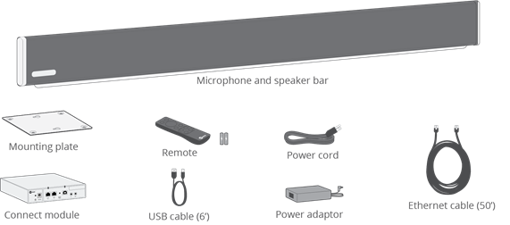
The Dual HDL300 system includes the same items as the single system with the addition of an extra Integrated microphone and speaker bar and a second Ethernet cable.
The upgrade HDL300 kit can be used to expand the single HDL300 system to a dual configuration. It is available with either a white (Dual-HDL300-W-U) or black (Dual-HDL300-B-U) grill color. The shipping box for the expansion kit will consist of the following items:
|
|
A dual HDL300 system can also be constructed from two single HDL300 systems, but there will be additional parts (connect module, remote, power adapter, etc.). Therefore, it is more efficient to construct the Dual HDL300 system with the proper upgrade kit. For more information, see our can more than one HDL300 system be installed to cover a larger space? article.
Orderable parts
A list of orderable parts for the HDL300 system can be found in our HDL300 system orderable parts article.
Standard connections of the HDL300 system
Connect module interfaces
Below is a diagram of the front face of the HDL300 system connect module. The following sections describe the connections from the left side to the right.
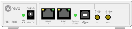
Power connector (+54C DC)
This port is used to connect to the provided power adapter.
Only use the power supply that is provided with this equipment. Failure to do so may result in electrical shock or other safety hazards.
RJ-45 connectors
There are two RJ-45 connector ports on the front of the connect module. For more information on how to use these ports, see our HDL300 system's RJ-45 connectors article.
USB
The HDL300 system connects to your computer through a USB port. For more information on the specifics of this port, see our HDL300 system's USB port article.
Auxiliary input (In) and auxiliary output (Out) Jacks
The connect module also has the option of connecting analog signals using the auxiliary input and output jacks instead of (or in combination with) the USB connector. The default configuration for the auxiliary jacks is for standard line-level audio input and output – as described in this section. The HDL300 system can also have these signals configured for mixed-mode, speaker mode and microphone level outputs. Details for using the auxiliary ports can be found in our using the auxiliary ports article.
Cabling for the HDL300 system
For installation of the product and cabling, follow all applicable country electrical codes, regional codes and local codes or ordinances.
Power adapter and cabling
Only use the power adapter that is provided with this equipment. The power adapter is an integral part of the safe and proper operation of the HDL300 system. Failure to use the provided power adapter may result in electrical shock or hazards or faulty operation of the unit.
The HDL300 system comes with a country-specific power cord to be used with the adapter. If this cord is not long enough to reach to a power outlet, you may use an extension cord or power bar. Only use extension cords, power bars and outlets that properly accommodate the equipment’s polarized/grounded plug. Make sure the extension cord complies with the safety regulations of the country or region. Do not use cheater plugs or any equipment that might defeat the purpose of the electrical ground.
Make sure any power cables used with the equipment are properly bundled, routed, covered or constrained if they cross the floor or pose a tripping hazard.
Ethernet cabling
All HDL300 systems include one 15 m (50’) general-purpose SSTP (screened shielded twisted pair) 26 AWG cable as the PoE cable. It is used to connect the connect module to the HDL300 integrated microphone and speaker bar. However, since the protocol is exclusive for the HDL300 system these ports cannot be directly connected to standard Ethernet ports (IEEE 802.3) on computer networks.
If you need an Ethernet cable longer than the one included in the system, see our I need an Ethernet cable longer than the 50’ (15 m) cable provided article.
Make sure the installation methods follow specific local or country codes or regulations. The cables provided with the HDL300 system are not plenum or riser rated. If the installation is in an air-handling space or between building floors, proper cabling will need to be obtained. For these specific applications, use cables that meet the appropriate safety and regulatory requirements and follow the applicable local or country codes or regulations. Use a trained electrician or expert to install the plenum or riser-rated cabling.
Ethernet Routers and Switches
The communication link between the connect module and an integrated microphone and speaker bar is based on PoE and will not work on standard IP networks. Therefore, these ports should not be connected to Ethernet routers. Additionally, Ethernet network switches (non-mechanical switches) may seem to operate correctly when inserted between the connect module and integrated microphone and speaker bar, but complications or errors may occur during firmware updates or system resets. Therefore, Ethernet network switches should not be used.
Mechanical Ethernet switches can be used if they support a minimum of 10/100 Base-T Ethernet standard and pass PoE power. More information about the uses of Mechanical Ethernet switches can be found in the Configuring a Dual HDL300 for divisible rooms article.
USB cabling
The system comes with a 6′ (2 m) USB cable that connects the connect module to your computer or host system. The cable is a USB A-male (to connect to the host/computer) to USB B-male (to attach to the connect module). If a longer cable is needed, use a USB 2.0 Hi-Speed cable that reaches lengths of up to 16.4′ (5 m). We do not recommend using USB cable extenders or hubs to increase the USB cabling distance, as they negatively affect the audio experience by increasing latency and dropping packets. If necessary, we recommend installing the connect module close to the computer or host device and using a longer Ethernet cable from the integrated microphone and speaker bar to the connect module.
Audio jack cabling
As the signal and cable are single-ended, keeping the cabling length to a maximum of 6 feet to ensure minimum noise is coupled onto the signal. Avoid running noisy cables next to these audio cables so coupling does not occur. Installing the connected equipment next to the connect module will help make sure this happens.
Connect
Connecting your HDL300 system
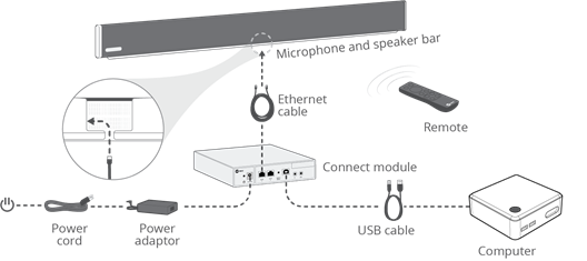
Below are interface connections for a standard HDL300 system configuration.
Standard configuration
The HDL300 system is intended primarily to be connected to a USB host (such as a computer) running a UC&C client or SIP dialing software. Below is the connection diagram of a basic system. When connecting the computer to USB, ensure that the playback and recording devices within your operating system and software are set to the HDL300 – Echo Canceling Speakerphone by default.
External microphones
Voice Amplification Mode has been added to HDL300 and Dual HDL300 audio conferencing systems. With this addition, which is currently available in public beta, the HDL300 systems solve the problem of supporting in-room amplification of an instructor or presenter's voice, while simultaneously providing full-room microphone pickup of in-room voices. Please see the articles below for additional information about Voice Amplification Mode.
External speakers
External speakers can be used with the HDL300 system. For more information, see the Using external speakers with Nureva conferencing systems article.
Session Initiation Protocol software options
The HDL300 system does not have a built-in SIP dialer, but it can enable SIP dialing with the help of other products. The HDL300 system can provide microphone and speaker functionality for a SIP-enabled device provided the device has compatible ports. For more information, see the Does the HDL300 system support session initiation protocol (SIP) software?
Dante interoperability
The HDL300 system does not directly support Dante software, but external adapters can be used to configure the HDL300 system to support it. The adapters can be connected through the analog input and output ports of the connect module. Nureva® Console software must have the auxiliary connections configured properly to allow for “Microphone out” (line level) and “Speaker Input.”
For more information, see the is the HDL300 system compatible with Dante software? article.
Installing the HDL300 system with the Nureva Wall
For instructions on how to install the HDL300 system with your Nureva Wall, see our installing the HDL300 system with the Nureva Wall article.
Installing a Dual HDL300 system
For instructions on installing your Dual HDL300 system, see our installing a Dual HDL300 system article.
Switching between a single HDL300 and Dual HDL300 installation
A switchable configuration may be useful in a meeting room with a movable divider, partition, wall, or door. In this case, the unit may be switched to Dual HDL300 system operation when the meeting area is configured to the larger size, and single operation when it is divided into two smaller rooms.
For instructions on how to set up this type of configuration, see our Configuring a Dual HDL300 for divisible rooms article.
Calibrate
System calibration
The HDL300 system has two types of calibration – automatic calibration and fast calibration. For more information, see our calibrating your HDL300 system article.
Testing
Testing the HDL300 system
Testing the speakers
With Nureva Console client, a sound test can be used to confirm that the system's speakers are connected. The Play sound test feature can be found in Device settings, under the Speakers menu. To further test or debug the HDL300 system's speakers, see the steps in our How can I test my HDL300 system's speakers and microphone? article.
Testing the microphone
To test the HDL300 system's speakers, see the steps in our How can I test my HDL300 system's speakers and microphone? article.
Testing the system with a UC&C client
Set up a test call with the UC&C Client to make sure the entire system operates together. Many UC&C clients have built-in test software such as Skype for Business. Refer to your UC&C instructions for further details.
Location
For details on where to install the microphone and speaker bar, see the following articles:
Software
Software and HDL300 system compatibility
Technical requirements
To view a list of operating systems compatible with the HDL300 system and driver requirements, see our technical requirements.
Universal communication and collaboration (UC&C) client requirements
For tips on using your HDL300 system with your UC&C client, see our Recommended settings for audio and video conferencing software article.
Upgrading your firmware
Firmware upgrades are primarily managed through Nureva Console. If you need to perform a manual update to your HDL300 system, please contact Nureva Technical Support.
Once the download is complete, open the file to launch the wizard. Make sure the HDL300 system is powered up during the installation process. Follow the instructions on the setup wizard to complete the firmware update.
For the best results, we recommend updating through Nureva Console.
Nureva Console
Nureva Console is software that is included with your HDL300 system. This software has two components, Console client and Console cloud. The client version of the software is installed on the in-room computer. The cloud version is accessible by navigating to https://console.nureva.com using a supported browser.
Use Nureva Console to change device settings, update the firmware, and test the system. With Nureva Console cloud device management is available remotely once an account is set up and a device is enrolled.